


編集部
English version Toragi Junior Test (16) [Correct answer and explanation] Preventing equipment shorts! Isolators that isolate input and output signals …… 英語版【トラ技ジュニア検定16】「機器のショートを防ぐ!入力と出力信号間を絶縁するアイソレータ」
![English version Toragi Junior Test (16) [Correct answer and explanation] Preventing equipment shorts! Isolators that isolate input and output signals …… 英語版【トラ技ジュニア検定16】「機器のショートを防ぐ!入力と出力信号間を絶縁するアイソレータ」](https://toragijr.cqpub.co.jp/wp-content/uploads/article/kentei/icatch_360x238_kentei2-1.gif)
ToraGi Junior No.60 (Winter 2025) p.37
“ToraGi Junior Test (16)” “Preventing equipment shorts! Isolators that isolate input and output signals” is posted.
Please check the journal for the question text and figures.
<Hitoshi Miyazaki>
トラ技ジュニア No.60(2025冬号)p.37掲載
英語版【トラ技ジュニア検定⑯】「機器のショートを防ぐ!入力と出力信号間を絶縁するアイソレータ」の解答と解説を掲載します. 日本語版はコチラ
問題文および図については,誌面にてご確認ください. <宮崎 仁>
[Correct answer]
(a)
[Explanation]
The statements a through c describe the characteristics of the three types of isolators, and the statement d describes a common property that is not related to the type of isolator.
●Photoisolator Principle and Characteristics
The most basic photoisolator (photocoupler) configuration is shown in Figure 1.
Figure 1
Basic configuration of photoisolators (photocouplers)

The electrical signal (digital signal) input to the primary side is converted into an optical signal by a light emitting element such as an LED and transmitted to the secondary side, where it is restored to the original electrical signal (digital signal) by a light receiving element such as a phototransistor. The primary and secondary sides are electrically isolated, and only the signal is transmitted.
In the example shown in Figure 1, when the input signal is “L”, a current flows through the LED and the LED emits light, and when the input signal is “H”, no current flows through the LED and the LED turns off. This means that the “L” and “H” digital signals are converted into “light” and “off” optical signals.
On the light-receiving side, when light is received, the phototransistor conducts, current flows through the pull-up resistor, and the output digital signal becomes “L”. When no light is received, the phototransistor does not conduct, and the output digital signal goes “H”.
Photoisolators can be used from DC to AC, and photoisolators are suitable for isolating digital signals. However, the basic configuration shown in Figure 1 is simple and low-cost, but it cannot handle very high-speed digital signals.
Electronic components such as semiconductor devices, ICs, resistors, and capacitors generally have a long life span and can be used for several years to several decades if they are kept away from adverse conditions such as heat, humidity, and corrosive gases. However, some components, such as batteries and electrolytic capacitors that use internal chemical reactions, light bulbs that generate a lot of heat, and switches and motors that have contacts and mechanical moving parts, have a shorter life.
LEDs, which are light-emitting devices, have a long life, which is a characteristic of semiconductors. However, when an electric current is applied to emit light, slight defects occur in the internal crystal structure, which can cause a gradual degradation of luminous efficiency over time. Although LED lighting has a much longer life than incandescent or fluorescent lamps, it is known to gradually become dimmer over time. It should be noted that photoisolators using LEDs also have a shorter life than general ICs and passive components.
●Digital Isolators Principle and Characteristics
Another method is to transmit electrical signals through space between two conductors.
When two insulated conductor plates are placed facing each other, as in a capacitor, no DC signal is transmitted. However, an AC signal is transmitted by the electrostatic capacitance between the plates (capacitive coupling).
When two insulated coils are wound around the same magnetic path, as in a transformer, no DC signal is transmitted. However, the mutual inductance between the coils allows AC signals to propagate (magnetic coupling).
Capacitive coupling and magnetic coupling isolate DC signals and allow only AC signals to pass through. Since digital signals contain a large DC component, simply isolating the signal does not allow it to propagate properly. It is necessary to convert the signal to one that does not contain a DC component in some way.
For example, as shown in Figure 2, an AC carrier wave is used for modulation to eliminate the DC component, and then the signal is isolated with a capacitor.
Figure 2
Basic configuration of capacitively coupled digital isolator (modulated type)
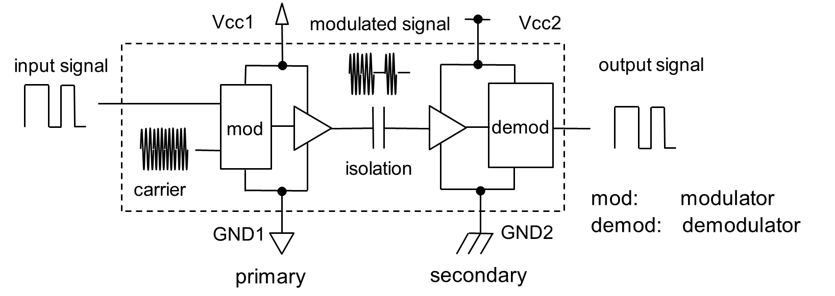
The modulation circuit on the primary side generates a modulated signal by removing the DC component from the digital signal.
The modulated signal that does not contain a DC component is isolated by a capacitor or transformer and transmitted to the secondary side.
The demodulation circuit on the secondary side converts the modulated signal back to the original digital signal.
The figure shows an example using modulation (carrier wave) and capacitor (capacitive coupling). There are several other methods.
The modulation method used in Figure 2 corresponds between “L” and “H” of the digital signal and “without” and “with” of the carrier wave.
In the modulation circuit, when the input signal is “L”, the modulation signal is “without carrier wave”, and when the input signal is “H”, the modulation signal is “with carrier wave”.
In the demodulation circuit, when the modulation signal is “without carrier wave”, the output signal is “L”, and when the modulation signal is “with carrier wave”, the output signal is “H”.
This isolates the primary and secondary sides, allowing only the AC carrier wave component to pass through the capacitor, resulting in the same digital signal at the output as at the input.
As shown in Figure 3, a transformer (magnetic coupling) is used in the insulating section, it is similarly insulated and transmits only the signal.
Figure 3
Basic configuration of capacitively coupled digital isolator (modulated type)
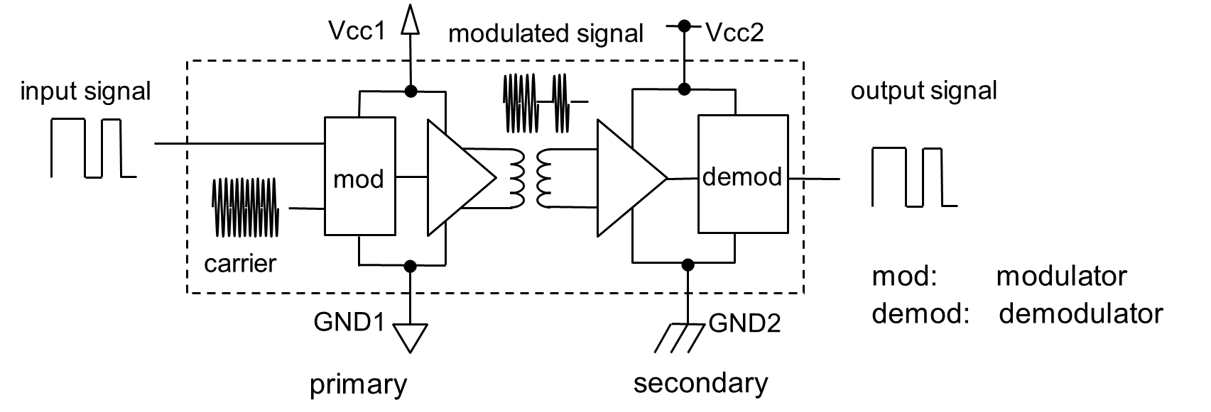
Example using modulation (carrier wave) and transformer (magnetic coupling).
Both capacitive-coupling and magnetic-coupling methods are simple in principle, but both require a circuit to remove the DC component from the digital signal. Previously (from the 1970s to the 1990s), optical coupling (photoisolators) were widely used because, in principle, they do not require DC rejection.
Recently, DC rejection circuits such as modulation circuits can be easily realized. Capacitive coupling and magnetic coupling methods are widely used as digital isolators.
A common feature of capacitively coupled and magnetically coupled systems is that the higher the AC frequency, the smaller the capacitor or transformer can be made, and the faster the digital signal can be handled.
Recent technologies can handle considerably high-frequency carrier waves. Capacitive-coupled and magnetically coupled systems are considered to have a slight advantage in terms of miniaturization of isolators and support for high-speed digital signals.
Furthermore, capacitive-coupled and magnetic-coupled systems have an advantage in terms of component life. However, conventional photoisolators (photocouplers) also have cost advantages if miniaturization and high speed are not required.
●For each option, consider whether it is correct or not
Consider the statements in the options, a through d, in the question.
a
Photoisolators have, in principle, a shorter lifetime than capacitively coupled types and magnetically coupled types. This is because the light intensity decreases due to degradation of the LEDs, which are the light-emitting elements.
As explained, this is a correct statement.
b
Capacitively coupled digital isolators isolate signals by means of a capacitor that absorbs high-frequency and smoothes the voltage. Therefore, they are, in principle, slower than optically coupled types or magnetically coupled types.
The capacitively coupled type uses a capacitor to transmit a high-speed AC signal. The part “by means of a capacitor that absorbs high-frequency and smoothes the voltage” is incorrect.
The higher the frequency, the lower the impedance of a capacitor. For this reason, high frequencies can be transmitted well when capacitors are used in series, as shown in Figure 4(a). This connection is used when capacitors are used for insulation.
On the other hand, as shown in Figure 4(b), when used across the wire and ground, the high-frequency component on the wire is shorted to the ground. The DC component is not short-circuited, but the AC component is absorbed and the voltage on the wire is smoothed. The fact that capacitors pass high frequencies does not change. However, the way of connection is different, and the function is completely different. The description in (a) confuses the two connections.
In principle, capacitively coupled isolators, which do not require conversion, have an advantage over optically coupled photoisolators, which convert electricity to light or light to electricity, or magnetically coupled isolators, which convert electricity to magnetism or magnetism to electricity, in terms of speed. In actual products, capacitively and magnetically coupled digital isolators are often high-speed, while optically coupled photoisolators are often low-speed.
Figure 4
Properties of capacitors and two connection methods
(a) Series connection

(b) Shunt connection

c
Like power transformers, magnetically coupled digital isolators are made by winding wires around a large, heavy iron core. Because of this, it is more difficult to make them smaller than optically coupled or capacitively coupled isolators.
Power transformers pass AC (50 Hz in eastern Japan and 60 Hz in western Japan) from commercial power sources and isolate DC. Because of the low frequency of AC, the number of turns is large and the core size is large to carry a large current, making the transformer large and heavy.
In contrast, digital isolators pass high frequencies, so the number of turns is small, and the current is small, so the core is small and light.
Magnetically coupled digital isolator products use coreless transformers with planar coils to achieve the same miniaturization as the capacitively coupled type. Therefore, the statement in c is incorrect.
d
When isolating signals between two circuits using isolators, the power lines and ground lines must be connected to each other, without isolation.
When the ground potentials of two circuits are different, direct connection of signal lines may cause malfunctions or failures due to large current flow or high voltage. To prevent this, insulation is used. In this case, not only signal lines but also ground and power supply lines must be insulated.
For example, in the case of the digital isolator shown in Figs. 2 and 3, there are ground and power supply pins to operate the modulation and demodulation circuits built into the isolator.
Since there are two pairs of power supplies: primary ground (GND1) and power supply (Vcc1), and secondary ground (GND2) and power supply (Vcc2), it is necessary to use separate, isolated power supplies as shown in Figure 5.
Figure 5
Isolation of ground and power lines
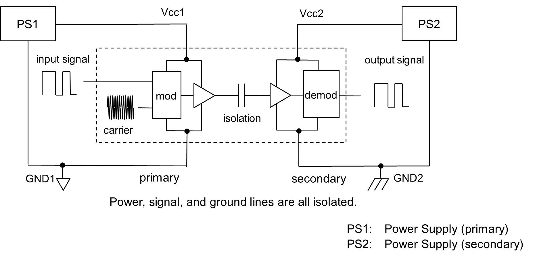
The basic photoisolator shown in Figure 1 has no ground or power supply terminals on the isolator itself. In this case, separate isolated power supplies must be used to provide the primary ground (GND1) and power (Vcc1) and the secondary ground (GND2) and power (Vcc2).
Therefore, it is incorrect to say that power and ground must be connected in common without isolation.
As explained above, the correct answer to this question is a, and b through d are incorrect.
